Official | HULFT IoT EdgeStreaming Reverse Reference First Edition: July 1, 2021
Execute processing based on the timing when specific columns are updated
This section describes how to use the monitoring table records function to execute a process based on the timing when specific columns are updated.
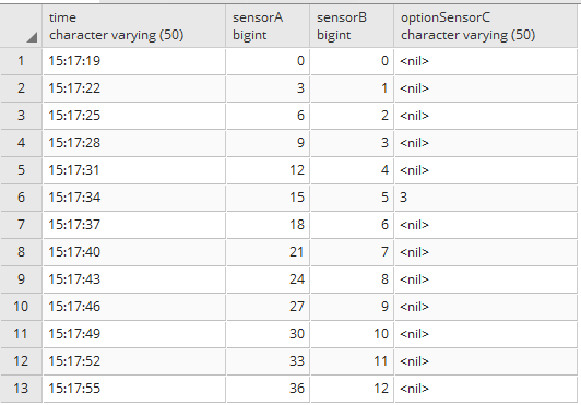
This process outputs results such as the following:
- Example
-
When monitoring how values are written to specific columns (column A, column B, and column C) of a temporary table and when the values are output to the database only after the values for column A, column B, and column C are all written.
-
When a value is written to only column A, nothing is output.
-
When values are written to only column A and column C, nothing is output.
-
When values are written to column A, column B, and column C, those values are output to the database.
-
Writing to the temporary table and the monitoring record function of the temporary table are combined, and processing takes place according to the timing when specific columns are updated.
The operation monitors how values are written to specific columns of a temporary table ("time," "sensorA," "sensorB," and "optionSensorC"), and the values for "time," "sensorA," "sensorB," and "optionSensorC" are output to the database when the values are written to the "time," "sensorA," and "sensorB" columns.
Here, the flow to create the processing is shown below.
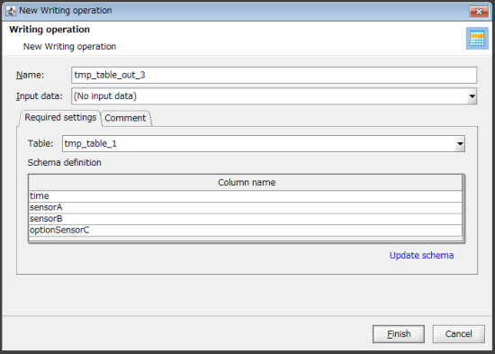
1. Create a temporary table that contains the following four columns: "time," "sensorA," "sensorB," and "optionSensorC."
The component icon that is used is Writing.
2. Create a process that obtains the current time and the automatically incremented number every second and writes the current time to the "time" column of the temporary table and the number to the "sensorA" column.
The component icons that are used are Periodic event and Writing.
3. Create a process that obtains the current time and the automatically incremented number every three seconds and writes the current time to the "time" column of the temporary table and the number to the "sensorB" column.
The component icons that are used are Periodic event and Writing.
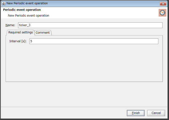
4. Create a process that obtains the current time and the automatically incremented number every five seconds and writes the current time to the "time" column of the temporary table and the number to the "optionSensorC" column.
The component icons that are used are Periodic event and Writing.
5. The values written using the stream flows of steps 2. , 3. , and 4. are joined with the "time" column as a key. Create a process that writes the current time and numbers to the database when the values are written to all three "time," "sensorA," and "sensorB" columns.
If a value is written to the "optionSensorC" column, the value is written to the database.
The component icons that are used are Monitoring records and Insert operation.
Key features (component icons)
- Writing
-
This component can be used to set the properties of the write operation.
It can be set from Basic > Temporary table > Writing of the tool palette.
- Periodic event
-
This component can be used to set the interval at which events are executed.
It can be set from Basic > Basic > Periodic event of the tool palette.
- Monitoring records
-
This component can be used to set the properties of the record monitoring operation.
It can be set from Basic > Temporary table > Monitoring records of the tool palette.
- Insert operation
-
This component can be used to set the properties of the insert operation to the database.
It can be set from Database > PostgreSQL > Insert of the tool palette.
Key features (Mapper logic)
- Current date/time (OS time zone)
-
This logic outputs the current date and time.
It can be set from Date > Basic > Current date/time (OS time zone) of the tool palette.
- Date/Time formatting(Standard format)
-
This logic formats the date and time to the selected format.
It can be set from String > Date > Date/Time formatting(Standard format) of the tool palette.
- Increment
-
This logic increases the value by one and outputs the result.
It can be set from Number > Basic > Increment of the tool palette.
Operation procedure
In this example, the processing that is described in Description of the processing is used.
1. Configure a temporary table setting (global resource).
-
From the tool palette, drag and drop Basic > Temporary table > Writing onto the script canvas.
The New Writing operation dialog box is displayed.
-
For Table on the Required settings tab, select Add.
The New Temporary table settings dialog box is displayed.
-
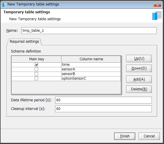
Configure a temporary table as shown below and click Finish.
-
Click Add, and create four columns with the column names time, sensorA, sensorB, and optionSensorC.
-
Select Main key of time to join the values with the "time" column as a key.
-
Enter a value in Data lifetime period and Cleanup interval.
In this example, "60" is entered for each.
-
-
Click Finish.
2. Create a stream flow so that the automatically incremented number and time are written to the temporary table every second.
-
Drag and drop Basic > Basic > Periodic event from the tool palette onto the script canvas.
The New Periodic event operation dialog box is displayed.
-
Enter "1" for Interval and click Finish.

3. On the script canvas, drag and drop the Periodic event icon onto the Writing icon.
If a message that prompts you to add mapping appears, click Yes.
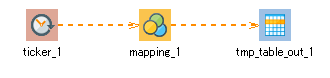
The mapping_1 icon and the stream flow are created.
4. On the script canvas, double-click mapping_1.
The Mapper editor is displayed.
5. Drag and drop the following logics from the tool palette onto the Mapper editor:
-
Date > Basic > Current date/time (OS time zone) (to obtain the current date and time)
-
String > Date > Date/Time formatting(Standard format) (to specify the date and time format that you want to output)
-
Number > Basic > Increment (to output the automatically incremented number)
The logics are placed on the Mapper editor.
6. Enter the property of the placed logic.
-
Double-click the Date/Time formatting(Standard format) logic.
The Date/Time formatting(Standard format) Logic Property dialog box is displayed.
-
Select a format from the Format pulldown menu.
In this example, hh:mm:ss is selected.
-
If necessary, also enter a comment in Comment and click Finish.
-
If necessary, double-click the Current date/time (OS time zone) logic and the Increment logic, enter a comment in Comment, and click Finish.
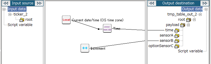
7. Drag and drop the Current date/time (OS time zone) logic onto the Date/Time formatting(Standard format) logic.
The mapping link from the Current date/time (OS time zone) logic to the Date/Time formatting(Standard format) logic is displayed.
8. Drag and drop the Date/Time formatting(Standard format) logic onto the output destination (time in this example).
The mapping link to time from the Date/Time formatting(Standard format) logic is displayed.
9. Drag and drop the Increment logic onto the output destination (sensorA in this example).
The mapping link to sensorA from the Increment logic is displayed.
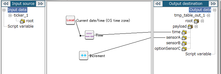
The configuration for mapping_1 is now completed. Return to the script canvas.
10. Specify the temporary table setting (global resource) created in step 1. .
-
From the tool palette, drag and drop Basic > Temporary table > Writing onto the script canvas.
The New Writing operation dialog box is displayed.
-
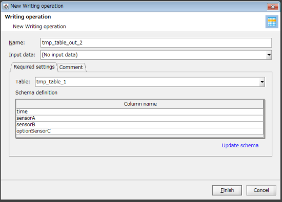
For Table on the Required settings tab, select the table created in step 1. .
-
Click Finish.
= Remarks =When you create a stream flow in the following steps, the name of the mapping icon is automatically entered for Input data. You don't have to specify this field.
11. Create a stream flow so that the automatically incremented number and time are written to the temporary table every three seconds.
-
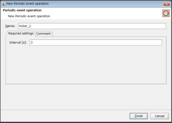
Drag and drop Basic > Basic > Periodic event from the tool palette onto the script canvas.
The New Periodic event operation dialog box is displayed.
-
Enter "3" for Interval and click Finish.
12. On the script canvas, drag and drop the Periodic event icon onto the Writing icon.
If a message that prompts you to add mapping appears, click Yes.
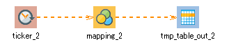
The mapping_2 icon and the stream flow are created.
13. On the script canvas, double-click mapping_2.
The Mapper editor is displayed.
14. Drag and drop the following logics from the tool palette onto the Mapper editor:
-
Date > Basic > Current date/time (OS time zone) (to obtain the current date and time)
-
String > Date > Date/Time formatting(Standard format) (to specify the date and time format that you want to output)
-
Number > Basic > Increment (to output the automatically incremented number)
The logics are placed on the Mapper editor.
15. Enter the property of the placed logic.
-
Double-click the Date/Time formatting(Standard format) logic.
The Date/Time formatting(Standard format) Logic Property dialog box is displayed.
-
Select a format from the Format pulldown menu.
In this example, hh:mm:ss is selected.
-
If necessary, also enter a comment in Comment and click Finish.
-
If necessary, double-click the Current date/time (OS time zone) logic and the Increment logic, enter a comment in Comment, and click Finish.
16. Drag and drop the Current date/time (OS time zone) logic onto the Date/Time formatting(Standard format) logic.
The mapping link from the Current date/time (OS time zone) logic to the Date/Time formatting(Standard format) logic is displayed.
17. Drag and drop the Date/Time formatting(Standard format) logic onto the output destination (time in this example).
The mapping link to time from the Date/Time formatting(Standard format) logic is displayed.
18. Drag and drop the Increment logic onto the output destination (sensorB in this example).
The mapping link to sensorB from the Increment logic is displayed.
The configuration for mapping_2 is now completed. Return to the script canvas.
19. Specify the temporary table setting (global resource) created in step 1. .
-
From the tool palette, drag and drop Basic > Temporary table > Writing onto the script canvas.
The New Writing operation dialog box is displayed.
-
For Table on the Required settings tab, select the table created in step 1. .
-
Click Finish.
= Remarks =When you create a stream flow in the following steps, the name of the mapping icon is automatically entered for Input data. You don't have to specify this field.
20. Create a stream flow so that the automatically incremented number and time are written to the temporary table every five seconds.
-
Drag and drop Basic > Basic > Periodic event from the tool palette onto the script canvas.
The New Periodic event operation dialog box is displayed.
-
Enter "5" for Interval and click Finish.
21. On the script canvas, drag and drop the Periodic event icon onto the Writing icon.
If a message that prompts you to add mapping appears, click Yes.
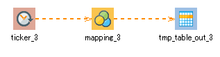
The mapping_3 icon and the stream flow are created.
22. On the script canvas, double-click mapping_3.
The Mapper editor is displayed.
23. Drag and drop the following logics from the tool palette onto the Mapper editor:
-
Date > Basic > Current date/time (OS time zone) (to obtain the current date and time)
-
String > Date > Date/Time formatting(Standard format) (to specify the date and time format that you want to output)
-
Number > Basic > Increment (to output the automatically incremented number)
The logics are placed on the Mapper editor.
24. Enter the property of the placed logic.
-
Double-click the Date/Time formatting(Standard format) logic.
The Date/Time formatting(Standard format) Logic Property dialog box is displayed.
-
Select a format from the Format pulldown menu.
In this example, hh:mm:ss is selected.
-
If necessary, also enter a comment in Comment and click Finish.
-
If necessary, double-click the Current date/time (OS time zone) logic and the Increment logic, enter a comment in Comment, and click Finish.
25. Drag and drop the Current date/time (OS time zone) logic onto the Date/Time formatting(Standard format) logic.
The mapping link from the Current date/time (OS time zone) logic to the Date/Time formatting(Standard format) logic is displayed.
26. Drag and drop the Date/Time formatting(Standard format) logic onto the output destination (time in this example).
The mapping link to time from the Date/Time formatting(Standard format) logic is displayed.
27. Drag and drop the Increment logic onto the output destination (optionSensorC in this example).
The mapping link to optionSensorC from the Increment logic is displayed.
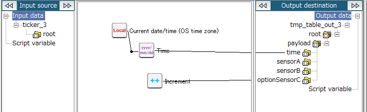
The configuration for mapping_3 is now completed. Return to the script canvas.
28. Create a stream flow that outputs the values to the database when values are written in all three columns ("time," "sensorA," and "sensorB") of the temporary table.
-
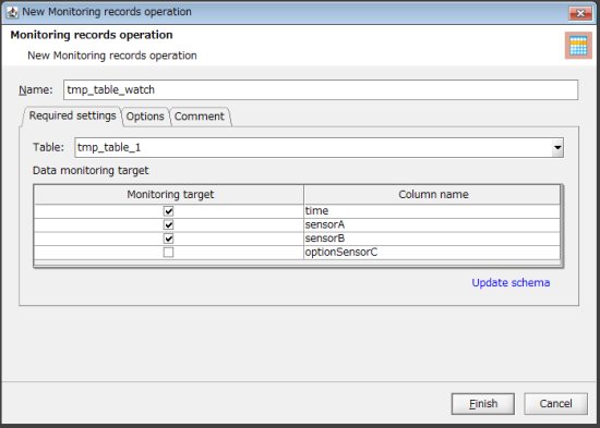
From the tool palette, drag and drop Basic > Temporary table > Monitoring records onto the script canvas.
The New Monitoring records operation dialog box is displayed.
-
Set the targets for monitoring as follows:
-
For Table on the Required settings tab, select the temporary table created in step 1.
-
For Monitoring target, select the following columns in Data monitoring target.
-
time
-
sensorA
-
sensorB
-
-
-
Click Finish.
29. Set the database to which the data is output.
-
Drag and drop Database > PostgrSQL > Insert from the tool palette onto the script canvas.
The New Insert operation dialog box is displayed.
-
Configure the settings on the Required settings tab.
-
Click Finish.
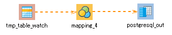
30. On the script canvas, drag and drop the Monitoring records icon onto the Insert operation icon.
If a message that prompts you to add mapping appears, click Yes.
The mapping_4 icon and the stream flow are created.
31. On the script canvas, double-click mapping_4.
The Mapper editor is displayed.
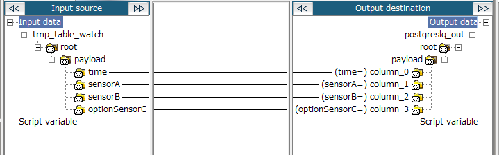
32. Drag and drop the following items from the input source onto the output destination:
-
time of the input source to time of the output destination
-
sensorA of the input source to sensorA of the output destination
-
sensorB of the input source to sensorB of the output destination
-
optionSensorC of the input source to optionSensorC of the output destination
33. Save the script.
For information about how to save a script, refer to First Step Guide.
The following result is obtained if you execute the script:
Official | HULFT IoT EdgeStreaming Reverse Reference First Edition: July 1, 2021